To complete my Engineering Honors program I conducted undergraduate research on underactuated electromechanical variable buoyancy autonomous underwater vehicles. I investigated the dynamics, controls, and navigation of the robot BOB. Below is a summary and detailed explanation of my contributions to the project.
Contribution
Summary
Build
Contribution:
- Integrated electronic components to control the volume within a custom-designed syringe to change the relative buoyancy of the robot.
Method:
- Determined necessary COTS electronics to control the volume in the syringe.
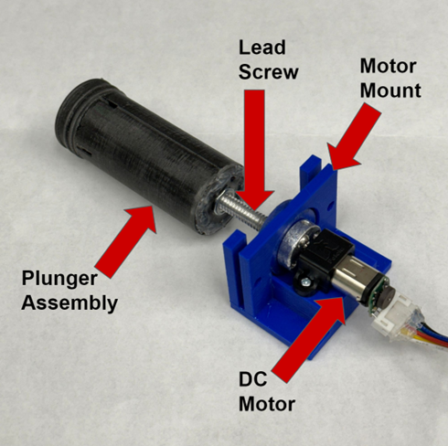
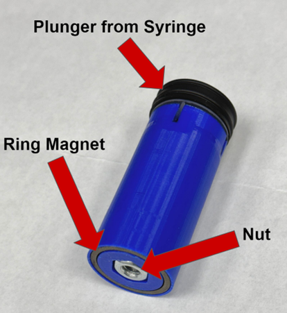
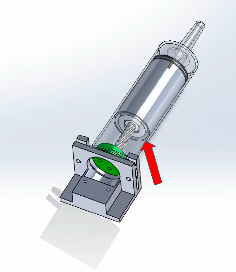
- Developed a mechanism to translate the rotational motion of the motor into the translational motion of the plunger.
- Troubleshoot electronics with a multimeter and oscilloscope.
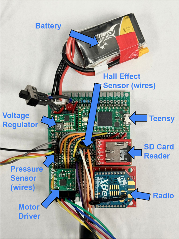
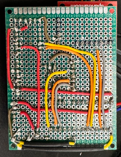
Result:
- Electronics and mechanisms were reliable and tested. Fifteen robots were purchased using this platform.
Simulation
Contribution:
- Simulated robot’s dynamics in Matlab simulation.
Method:
- Created a simulation using MATLAB state-space model and MATLAB’s ode45 numerical integrator.
- Utilized LQR controller to find optimal gains for full-state feedback control.
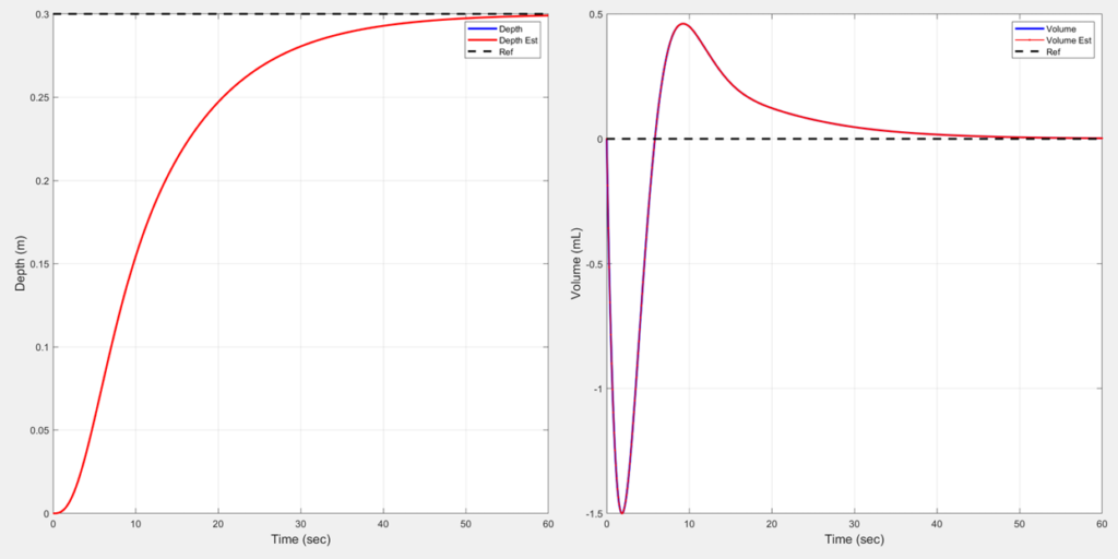
Result:
- Simulated controls reached critical damping at goal depths
Pressure-Depth Map
Contribution:
- Constructed a pressure-depth map for navigating to various depths underwater.
Method:
- Conducted a linear regression by averaging pressure at different depths.
Result:
- Accurately measured depth within

Controls
Contribution:
- Tuned PD feedback controller to settle at the desired depth.
Method:
- Progressively integrated different controllers in real trials.
- First with a proportional controller until even oscillations then slowly incorporating a derivative term until the oscillations are damped, settling at the goal.
Result:
- The robot settled within 10 cm of the goal depth

Comprehensive Review
Introduction
BOB was to develop an affordable and easily mass-produced fleet of autonomous robots for studying underwater currents and ocean ecosystems. With multiple robots deployed to various depths, underwater systems could be modeled. The robot is currently being refined and utilized in research projects at the University of Maryland and its satellite campuses.
Build
Platform
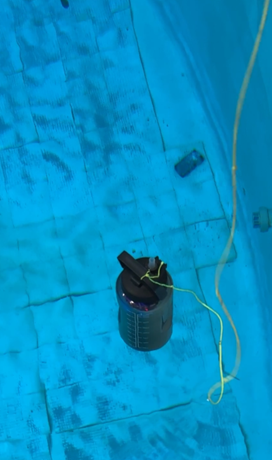
The electronics of BOB are housed inside a 64 oz water bottle. A 60 mL syringe nozzle is epoxied through the bottle’s lid for water intake and expulsion.
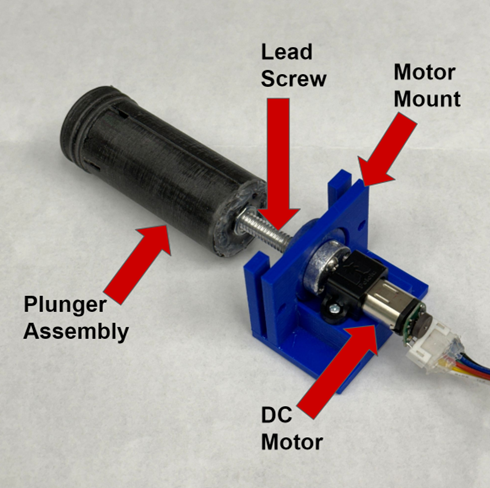
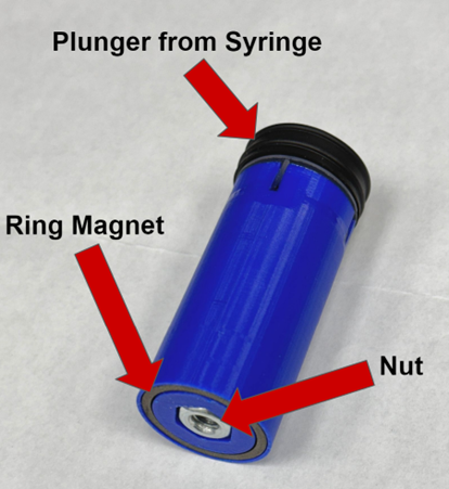
The syringe plunger, replaced by a 3D-printed plunger assembly, connects to a lead screw attached to a DC motor. This setup converts motor rotation into linear motion, controlling the syringe’s volume, which is reduced to a working capacity of 20 mL. Lead weights at the bottle’s bottom provide neutral buoyancy when 15 mL of water is in the syringe.
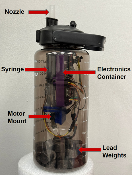
Hardware
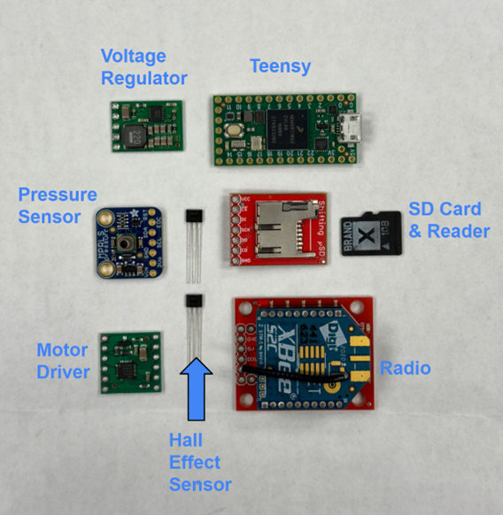
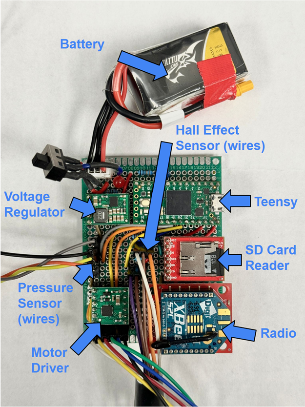
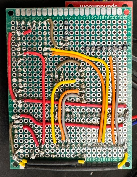
This section outlines the electronics needed for BOB and their roles. The microcontroller runs C-style code, processes sensor data, and communicates with a computer above water via an XBee radio and MATLAB. The XBee relays scientific data and receives control commands. The magnetic encoder tracks the motor’s rotations to calculate the water volume in the syringe.
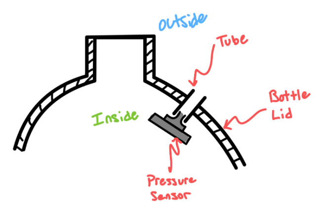
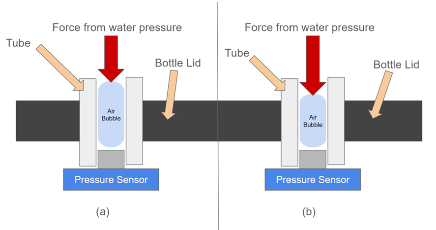
A barometric pressure sensor, mounted on the bottle’s lid, measures air pressure in the tube to determine the depth. The microcontroller then adjusts BOB’s depth by sending PWM signals to the motor driver, controlling the intake or expulsion of water.
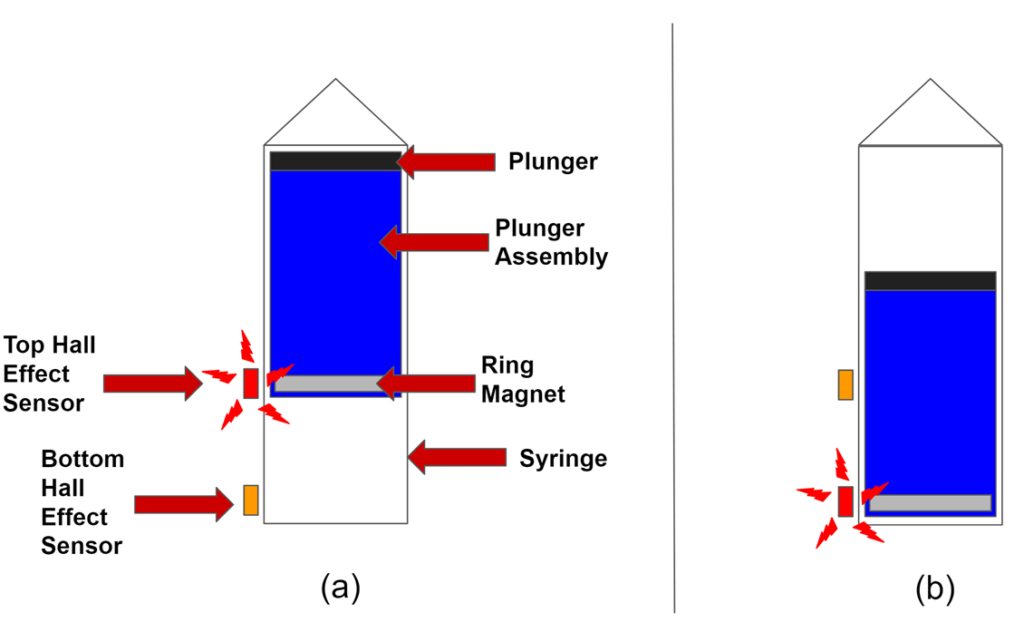
The plunger assembly contains a ring magnet and two hall effect sensors, which limit the syringe’s movement. These sensors prevent overextension of the motor and help zero the encoder’s position, ensuring accurate volume calculations.
| Name | Part | Role |
|---|---|---|
| Battery | 11.1V, 0.45 Ah | Power system and motor |
| Microcontroller | Teensy 4.0 | Read in data and output PWM signals |
| Voltage Regulator | 5V, 1A Step-Down | Convert 12V from battery to 5V for MC |
| Motor | 12V Brushed DC Motor | Move plunger of syringe |
| Motor Driver | Single Brushed DC Motor Driver | Control speed and direction of the motor |
| SD Card Reader | microSD Breakout | Read and write data to SD card |
| SD Card | 1 GB microSD | Contain data from trials |
| Radio | XBee S2C | Communicate with MATLAB Control Panel |
| Pressure Sensor | MPRLS Ported Pressure Sensor | Read the pressure at depth |
| Hall Effect | Hall Effect Sensor | Detect magnet within syringe |
| Encoder | Magnetic Encoder | Control the speed and direction of the motor |
Pressure-Depth Map
To determine BOB’s current depth, the hydrostatic equation is used, which relates pressure difference to depth in a fluid. Using the average values for water density (997 kg/m³) and gravity (9.81 m/s²), the depth can be calculated by rearranging the hydrostatic equation as:
![]()
However, BOB measures the air pressure inside a tube rather than water pressure directly, which affects the accuracy. To correct this, BOB is lowered to known depths (up to 2.25 meters), and the pressure is recorded at 0.25-meter intervals. A linear regression is then performed to establish a new constant for the pressure-depth relationship.
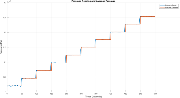
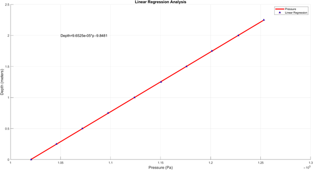
The new constant for the linear equation is 9.653×10−59.653 \times 10^{-5}9.653×10⁻⁵ m³/kg, replacing the ideal value. This regression shows a high correlation (R² = 0.999), making it reliable. Instead of using a fixed y-intercept for atmospheric pressure, BOB takes real-time atmospheric readings at the start of each experiment for accuracy. Using the revised equation:
![]()
Tests show that the calculated depth is accurate within ±1 cm, sufficient for BOB’s depth measurements.
Dynamics
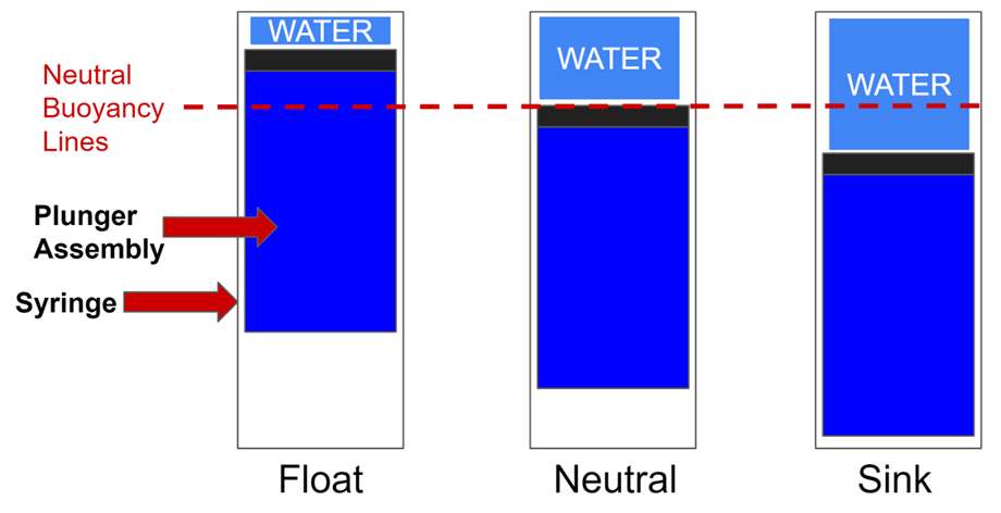
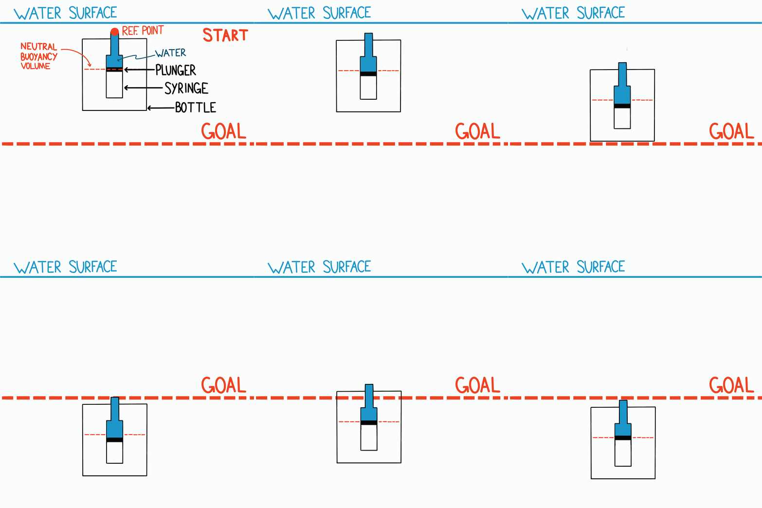
The section describes the dynamics governing BOB’s movement through water. The system’s buoyancy force (BvB_vBv) is variable, influenced by the volume of water in the syringe. Lead weights are used to achieve neutral buoyancy at 15 mL of water, meaning BOB should remain at its current depth without sinking or floating. However, imperfections in buoyancy due to bottle deformation at high pressures and sensitivity in weight trimming make the system unstable, requiring a controller to maintain stability.
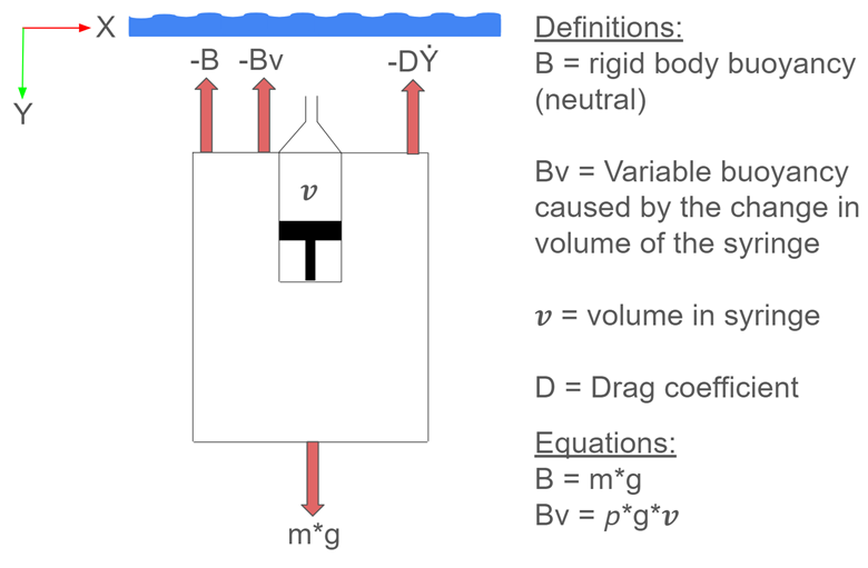
The variable buoyancy force changes based on the syringe’s volume relative to 15 mL. If less than 15 mL of water is present, BOB floats; if more, BOB sinks. With exactly 15 mL, there is no net force, and BOB is neutrally buoyant.
The equation of motion for vertical movement is derived by summing forces in the Y-direction:
![]()
To account for the motor dynamics, volume is added as a state variable, introducing two new equations for motor shaft angle ![]()
![]()
![]()
Where:


The updated state-space model is:

Simulation
A simulation was developed in MATLAB using a state-space model of BOB’s dynamics. An LQR controller was applied to determine optimal gains for the system. The Q matrix penalized depth, depth rate, and volume, while the R-value controlled actuator voltage. The simulation showed BOB reaching a reference depth of 0.3 meters within 60 seconds, with no overshoot or steady-state error.

However, experimental testing revealed instability due to a change in static buoyancy caused by a deflection in the bottle’s walls. Instead of modeling these dynamics and building them into the controller a more robust bottle could mitigate the issue. Tuning a single-state feedback controller on hardware is investigated in the next section.
Controls & Experimentation
A single-state feedback controller was investigated to control BOB’s movement vertically in water. Using the error between BOB’s current depth and the goal depth, we can calculate the output motor voltage to move the plunger changing the variable buoyancy force. The controller used was a Proportional-Derivative (PD) controller. The proportional component of the controller moves BOB toward the goal while the derivative term slows BOB’s movement reducing overshoot.

To tune the controller, the proportional controller was slowly increased until the bottle showed steady oscillations. Then the derivative term was slowly integrated until the oscillations dampened. A low-pass filter was incorporated to limit the reactivity of the derivative controller to noise from the pressure sensor. The results of a trial are shown below.


BOB settled within 10 cm of the goal depth at 0.3 meters. To reduce the steady-state error an integral term could be introduced. This term would push BOB towards the goal when the proportional aspect of the controller did not have a large enough value to actuate the motor. Unfortunately, I was unable to get the controller to include the integral term before graduation, and do not have experimental results showing this.
Underwater image: https://stock.adobe.com/images/3d-rendered-illustration-of-sun-light-rays-under-water/143932362
