Satellite attitude control is a crucial factor in their operation. Taking advantage of “zero” gravity, spacecraft can orient themselves by manipulating the angular momentum of a Control Moment Gyroscope (CMG). CMGs are composed of flywheels, spun to build angular momentum, and gyroscopes, used to manipulate the orientation of the flywheels. By maneuvering the flywheels in certain directions we can impart torque on the spacecraft, changing its orientation.
For this project, I am building a simulation to test and tune the control of a double-gimbal scissored-pair CMG for object tracking in Low Earth Orbit (LEO) using a 3U CubeSat platform.
Hirohisa Kojima, Reiji Nakamura, Sajjad Keshtkar,
Steering control law for double-gimbal scissored-pair CMG,
Advances in Space Research, Volume 66, Issue 4, 2020, Pages 771-784, ISSN 0273-1177,
https://doi.org/10.1016/j.asr.2020.05.007.
Project Overview
- Build a simulation in MATLAB and implement the control scheme from this paper.
- Animate the orientation of the spacecraft and double-gimbal scissored-pair CMG.
- Test control scheme from the paper on moving targets.
- Migrate the simulation to MATLAB Simulink.
- Incorporate a 3-axis gyroscope to simulate sensor noise.
- Determine the slew rate necessary for tracking objects in space.
- Scale CMG to work on CubeSat-sized spacecraft.
- Refine controls for the current satellite setup.
- Place into orbit and evaluate perturbations along with Earth surface tracking.
Satellite Control
The input to the first controller is based on the satellite’s orientation, determining if the satellite’s reference frame is aligned with the goal reference frame.
To describe the satellite’s orientation quaternions will be used as they avoid the singularities that Euler angles are prone to.
Input: Error between current quaternion and goal quaternion
Output: Command torque on the spacecraft
CMG Control
With a command torque on the spacecraft calculated from the difference in orientation, the CMG will begin to manipulate the angular momentum to rotate the satellite.
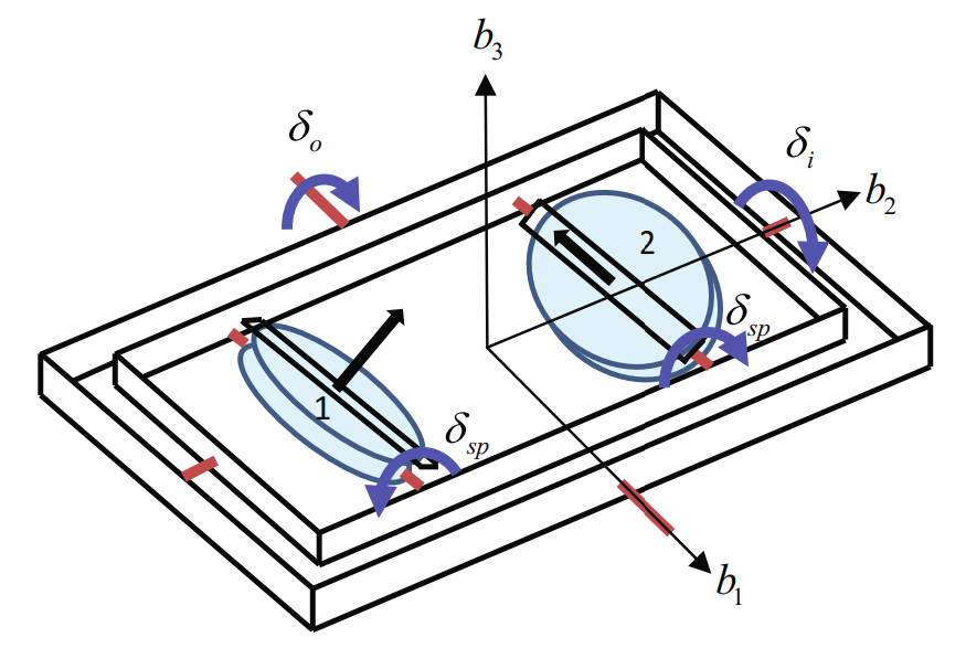


Despite the use of quaternions for the satellite, the gimbals of the CMG still have a few singularities that result in gimbal lock.
Singularities occur when:


Singularity 
To recover from this singularity the inner and outer gimbals are rotated to align the output torque of the CMG with the goal quaternion. Then the flywheels are rotated to impart a torque and the satellite begins to move towards the target, eventually slowing the satellite by rotating the flywheels back to their initial position
Singularity 
To eliminate most of the singularities ![]()
![]()
![]()
When the satellite is near ![]()
MATLAB Simulation
To simulate the satellite dynamics and controls I used MATLAB Ode45 numerical integration solver. Integrating the quaternion rate (![]()
![]()
![]()
Initial Conditions:
Goal:
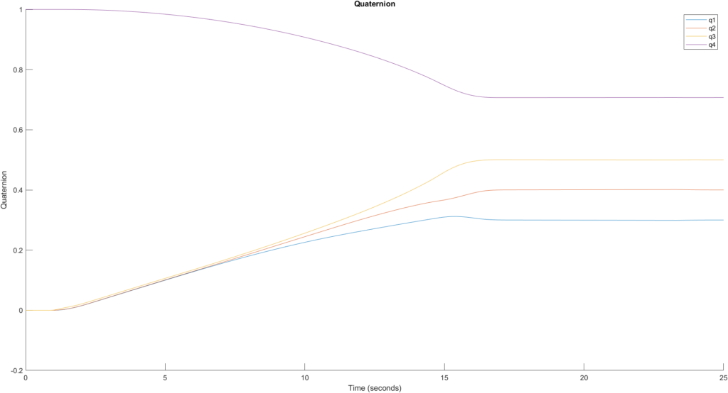
From the output, we can see it settled in about 17.5 seconds at the goal state.
Moving Targets
To analyze the current control scheme’s ability to track objects, I slowly moderated the initial quaternion target of ![]()
![]()
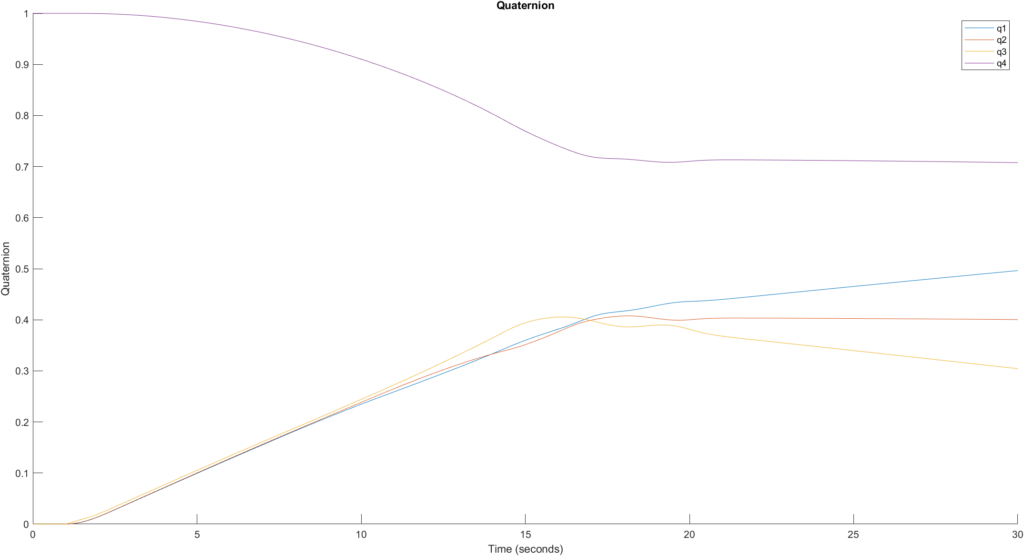
The system will have to be analyzed further for expected required slew rates of targets on Earth’s surface or in space.
Animation
Simulink
Converted the system over to MATLAB Simulink. Incorporated Simulink 3-axis gyroscope to calculate the satellite’s angular velocity rather than integrating to incorporate sensor noise.
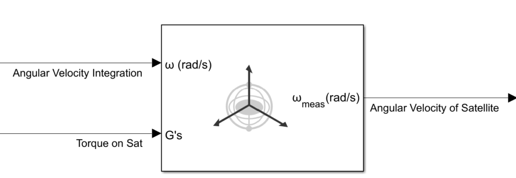
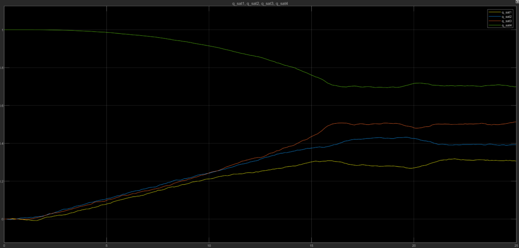
The noise introduced by the gyroscope degrades the controller’s performance. To mitigate this, state estimation methods such as the Kalman filter or a low-pass filter will be explored to improve the satellite’s response and behavior.
System Design
We must first define the satellite’s attitude requirements to scale the current double-gimbal scissored-pair CMG to fit within a CubeSat-scale satellite.
Typical slew rates (change in angle per second) range from ![]()
![]()
![]()
![]()
A simple analysis of an equatorial LEO orbit tracking a storm moving west would have to track at a minimum of ![]()
![]()
Designing between ![]() range is optimal for testing both conditions. Starting, the design will be targeted at
range is optimal for testing both conditions. Starting, the design will be targeted at ![]()
A slew rate ![]()
![]() turn in 9 seconds. Using the equation below we can find the necessary angular acceleration.
turn in 9 seconds. Using the equation below we can find the necessary angular acceleration.
![]()
![]()

We can find the required torque of the CMG from the angular acceleration.
![]()

The needed wheel torque is ![]() . The flywheels provide the maximum torque at
. The flywheels provide the maximum torque at ![]() .
.
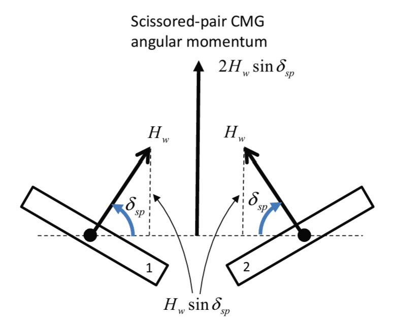
The torque output is controlled by two variables ![]() , the angular momentum of the wheel, and the gimbal angle rate respectively.
, the angular momentum of the wheel, and the gimbal angle rate respectively.
![]()
The old ![]() will be used at
will be used at  . Now the double-gimbal scissored-pair CMG has to be sized to fit with a 3U CubeSat and provide the necessary angular momentum
 ![]() . Our satellite is modeled after the MiRaTA satellite. The MiRaTA’s mass was 6 kg but to account for unknowns our satellite will be 8 kg with the same envelope size of 10x10x34 cm. Considering there are two flywheels the angular momentum of a singular flywheel
. Our satellite is modeled after the MiRaTA satellite. The MiRaTA’s mass was 6 kg but to account for unknowns our satellite will be 8 kg with the same envelope size of 10x10x34 cm. Considering there are two flywheels the angular momentum of a singular flywheel ![]() is found below.
is found below.
![]()

With CubeSat’s limited power budget, the flywheel in our case will be spun at 5,000 rpm and made of aluminum 6061. Material research was limited to concentrate on the important aspects of this project. The disk will be 2.32 cm in radius and 0.5 cm in thickness to meet the required angular momentum. Building the double gimbal around these flywheels leaves ample room inside the satellite’s body.
In total, we resized the CMG to fit within a 3U CubeSat body and give the required slew rate of ![]() for Earth surface object tracking and relative motion tracking.
for Earth surface object tracking and relative motion tracking.
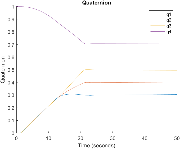
| System Performance | Spec |
|---|---|
| Average Slew Rate ( | 3.5 |
| Max Slew Rate ( | 5.4 |
| Settling Time (seconds) | 20.2 |
| Steady-State Error | 0.02 |
V.J. Lappas, W.H. Steyn, C.I. Underwood,
Attitude control for small satellites using control moment gyros,
Acta Astronautica, Volume 51, Issues 1–9, 2002, Pages 101-111, ISSN 0094-5765,
https://doi.org/10.1016/S0094-5765(02)00089-9.
Adjusting Controls for New Satellite
The gains in our control system are listed below.
| Gain | Purpose | Old Design Value |
|---|---|---|
| Moving the gimbals | 9.0 | |
| The influence of satellite angular velocity on moving the gimbals | 5.4 | |
| Returning rotors to initial position when approaching goal | 1.0 | |
| Moving the scissored pair during null motion | 10.0 |
Equations (2) and (3) define the gains ![]() and
and ![]() . These were found by linearizing the dynamic equation that governs the CMG (1).
. These were found by linearizing the dynamic equation that governs the CMG (1).
![]()
![]()
![]()
![]()
![]()
![]()
(1)
(2)
(3)
Where ![]() is the angular natural frequency and
is the angular natural frequency and ![]() is the damping ratio, each with values of 3.0
is the damping ratio, each with values of 3.0 ![]() and 0.9 respectively.
and 0.9 respectively.
Without the controller’s input, the system has no natural frequency or damping ratio so we can apply desired values through the controller.
![]() and
and ![]() gain values would depend on avoiding saturation of the actuators so for now they will remain the same as the paper’s values.
gain values would depend on avoiding saturation of the actuators so for now they will remain the same as the paper’s values.
This leaves us with only having to design the natural frequency and damping ratio for the system, simplifying our controller.
For now, to find the optimal coupled values we can automate the program to iterate through possible pairs. Damping ratios from 0.5 to 1 are considered, and natural frequencies greater than 1 but less than 10. Note that the natural frequency of the system matters less as the damping ratio approaches 1.
After iterating through I found a damping ratio of 0.7 and a natural frequency of 2 rad/s resulted in the best settling time.
| New System Performance | Spec |
|---|---|
| Average Slew Rate ( | 3.4 |
| Max Slew Rate ( | 5.4 |
| Settling Time (seconds) | 19.5 |
| Steady-State Error | 0.02 |
Orbit Simulation
Continuing the simulation, I placed the satellite in an orbit with the following orbital elements. This orbit is temporary, just for testing the satellite’s controls in a simulated orbit.
| Orbital Element | Value |
|---|---|
| Semi-major axis (km) | 6,786 |
| Eccentricity | 0.01 |
| Inclination (degrees) | 50 |
| RAAN (degrees) | 95 |
| Argument of Periapsis (degrees) | 93 |
| True Anomaly Start (degrees) | 203 |
Above is an animation of the satellite pointing at a stationary ground station. The green line represents the satellite and ground station line of sight. We can export the target quaternion pointing angles from this simulation and test the current control setup.
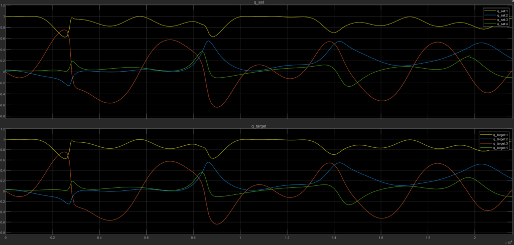
The top graph shows the current satellite orientation and the bottom graph shows the target orientation. From this we can see the satellite tracks the ground target closely, exact metrics will be delineated later.
When the satellite is not in the ground station’s line of sight, the controller will align the body axis with the Local Vertical Local Horizontal (LVLH) reference frame.
Simulation Details
MATLAB’s Simulink offers satellite dynamics and pointing requirements, but I found it more beneficial for learning and debugging to create the code and perform the calculations from scratch.
The general procedure is shown below.

Orbit Propagator
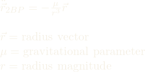
2 Body Problem
J2 Perturbation
![Rendered by QuickLaTeX.com \vec{\nabla}[\frac{\mu}{r}[1-J_{2}(\frac{R_{earth}}{r})^2(\frac{3}{2}\sin^2(\phi)-\frac{1}{2})]] \newline \newline J_{2} = J_{2}~\textnormal{constant} \newline R_{earth} = \textnormal{radius of Earth} \newline \phi = \textnormal{latitude of satellite}](https://fletchersmithportfolio.com/wp-content/ql-cache/quicklatex.com-f102e4ea9be82c181f388216b9a8cc5f_l3.png)
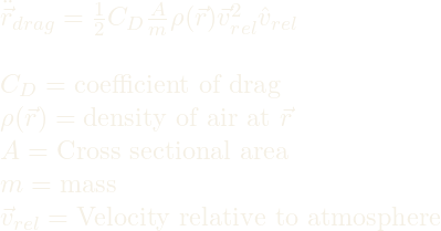
Atmospheric Drag
Attitude Propagator
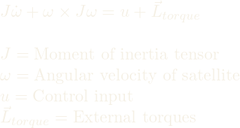
Euler’s Rotation Equation
Gravity Gradient Torque
![]()
Note: X means cross product
Line-of-Sight Equation

Pointing Equation
![]()
